ここでは、次の4種類のLQI制御系設計について述べます。
| Case | 設計モデル | 状態FB | 状態OB | 積分動作 | 注意点 |
| 1 | 5次 | 5次 | 未使用 | 要 | 「絵に描いた餅」 |
| 2 | 5次 | 3次 | 不要 | 要 | ヒーブのゲインを強制的に零 |
| 3 | 3次 | 3次 | 不要 | 要 | ヒーブからの連成を抑制できるか |
| 4 | 5次 | 5次 | 要 | 要 | コントローラが微分方程式 |
Note e12に示すように、データセットNo.1について、id=128の場合を設計用モデルとして採用したとき、Case2とCase3のどちらを用いても制御性能に大きな差異が見られません。そこでこのコントローラがどれくらいのモデル変動をカバーできるかという意味のロバスト性をシミュレーションにより調べてみます。ここで、モデル変動としては、前進速度を変える場合と、重心位置を変える場合の2通りを考えます。そのために次の3組のデータセットを考えます。
| 艇 | 艇質量[kg] | 長手方向重心位置[m] | 備考 | |
| No3 | SPTM247 | 2845 | 1.937 | 2022/1/19重量重心測定結果より |
| No4 | SPTM247 | 2945 | 1.937 | No3重量に+100kg |
| No5 | SPTM247 | 2745 | 1.937 | No3重量に-100kg |
設計用モデルとして、データセットNo.3における船外機取付角-2[deg]のときのid=128の場合を採用し、Case 2とCase 3のLQIコントローラを設計します。そしてデータセットNo.3,4,5における船外機取付角-2[deg]のときのモデル(id=126~133)を安定化できるかを調べます。シミュレーション結果を次に示します。
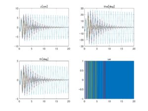 ⇒Case2:いくつかの動作点で不安定
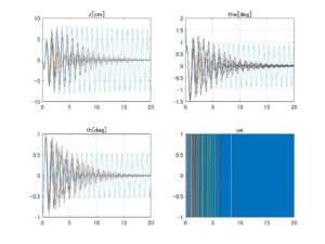 ⇒Case3:いくつかの動作点で不安定
図1 データセットNo.3の場合、LQIコントローラのロバスト性
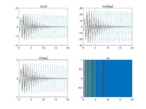 ⇒Case2:いくつかの動作点で不安定
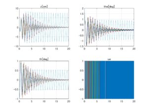 ⇒Case3:いくつかの動作点で不安定
図2 データセットNo.4の場合、LQIコントローラのロバスト性
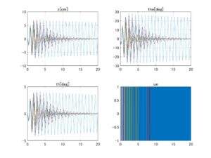 ⇒Case2:いくつかの動作点で不安定
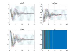 ⇒Case3:いくつかの動作点で不安定
図3 データセットNo.5の場合、LQIコントローラのロバスト性
これらのシミュレーションは本来は非線形シミュレータ上で行うべきですが、ここでは6次元線形モデルを用いて簡易的に行っています。
第1の注意点は、6次元線形モデルの第4番目の状態変数![]() の係数を強制的に
の係数を強制的に![]() としていることです。これは
としていることです。これは![]() となる場合があって、
となる場合があって、![]() が発散してしまうからです。
が発散してしまうからです。
第2の注意点は、上のシミュレーションでは各データセットのすべてのモデルを安定化できていませんが、設計用モデルとして、データセットNo.1における船外機取付角-2[deg]のときのid=128の場合を採用すると、各データセットのすべてのモデルは安定化されることです。
これらの事情は、線形モデルが暫定版の非線形シミュレータから得られているので正確ではないためとも考えられます。いずれにしてもできるだけ実機のダイナミックスを反映した非線形シミュレータ上での再検討が必要になります。
| MATLAB |
|
| MATLAB |
|
Note e12 LQI制御系の設計
Case 1:5次元モデルに基づくLQI制御
●LQI制御系を設計するために、次の5次元モデルを考えます。
![Rendered by QuickLaTeX.com \displaystyle{(1.1)\quad \begin{array}{l} \underbrace{ \frac{d}{dt} \left[\begin{array}{c} z(t)-z^*\\ \theta(t)-\theta^*\\ \dot{z}(t)\\ \dot{\theta}(t)\\ \theta_e(t)-\theta_e^* \end{array}\right] }_{\dot{x}(t)} = \underbrace{ \left[\begin{array}{ccccc} 0 & 0 & 1 & 0 & 0\\ 0 & 0 & 0 & 1 & 0\\ a_{52} & a_{53} & a_{55} & a_{56} & b_{52}\\ a_{62} & a_{63} & a_{65} & a_{66} & b_{62}\\ 0 & 0 & 0 & 0 & 0 \end{array}\right] }_{A} \underbrace{ \left[\begin{array}{c} z(t)-z^*\\ \theta(t)-\theta^*\\ \dot{z}(t)\\ \dot{\theta}(t)\\ \theta_e(t)-\theta_e^* \end{array}\right] }_{x(t)}\\ + \underbrace{ \left[\begin{array}{c} 0 \\ 0 \\ 0 \\ 0 \\ \omega_e \end{array}\right] }_{B} u(t) \end{array}}](https://cacsd1.sakura.ne.jp/wp/wp-content/ql-cache/quicklatex.com-2ab91f82b36ff6c479a3662543135546_l3.png)
![Rendered by QuickLaTeX.com \displaystyle{(1.2)\quad \begin{array}{l} \underbrace{ \left[\begin{array}{c} \theta(t)-\theta^*\\ \dot{\theta}(t)\\ \theta_e(t)-\theta_e^* \end{array}\right] }_{y(t)} = \underbrace{ \left[\begin{array}{ccccc} 0 & 1 & 0 & 0 & 0\\ 0 & 0 & 0 & 1 & 0\\ 0 & 0 & 0 & 0 & 1 \end{array}\right] }_{C_M} \underbrace{ \left[\begin{array}{c} z(t)-z^*\\ \theta(t)-\theta^*\\ \dot{z}(t)\\ \dot{\theta}(t)\\ \theta_e(t)-\theta_e^* \end{array}\right] }_{x(t)} \end{array}}](https://cacsd1.sakura.ne.jp/wp/wp-content/ql-cache/quicklatex.com-ab495fc33213399c94bb22d35ea16aa7_l3.png)
ここで操作入力は![]() ではなく
ではなく![]() としていますが、制御系の評価の際に
としていますが、制御系の評価の際に
![]()
とします。
●制御対象YMCPBに対する制御目的は、あるスラスト![]() と取付角
と取付角![]() の下で、巡航速度
の下で、巡航速度![]() で走行するとき、一定の姿勢
で走行するとき、一定の姿勢![]() を保つこととします。制御目的を達成する制御則として次式を考えます。
を保つこととします。制御目的を達成する制御則として次式を考えます。
![]()
ここで、右辺第1項は状態フィードバック、第2項は船外機取付角をある収納状態![]() から所定の平衡入力値
から所定の平衡入力値![]() に設定するための積分動作です。いま
に設定するための積分動作です。いま
![Rendered by QuickLaTeX.com \displaystyle{(4)\quad \begin{array}{l} \theta_e(t)-\theta_e^* = \underbrace{ \left[\begin{array}{ccccc} 0 & 0 & 0 & 0 & 1 \end{array}\right] }_{C} \underbrace{ \left[\begin{array}{c} z(t)-z^*\\ \theta(t)-\theta^*\\ \dot{z}(t)\\ \dot{\theta}(t)\\ \theta_e(t)-\theta_e^* \end{array}\right] }_{x(t)} \rightarrow \theta_e^c=0\quad(t\rightarrow\infty) \end{array}}](https://cacsd1.sakura.ne.jp/wp/wp-content/ql-cache/quicklatex.com-b608779184f29f7dfe7199146bb182ff_l3.png)
となって、船外機取付角を設定値![]() に維持できたとすると、次式が成り立つ必要があります。
に維持できたとすると、次式が成り立つ必要があります。

すなわち
![Rendered by QuickLaTeX.com \displaystyle{(4')\quad \left[\begin{array}{c} 0 \\ 0 \\ 0 \\ 0 \\ 0 \\\hline \theta_e^c \\ \end{array}\right] = \underbrace{ \left[\begin{array}{ccccc|c} 0 & 0 & 1 & 0 & 0 & 0\\ 0 & 0 & 0 & 1 & 0 & 0\\ a_{52} & a_{53} & a_{55} & a_{56} & b_{52}& 0\\ a_{62} & a_{63} & a_{65} & a_{66} & b_{62}& 0\\ 0 & 0 & 0 & 0 & 0 & \omega_e\\\hline 0 & 0 & 0 & 0 & 1 & 0 \end{array}\right] }_{S= \left[\begin{array}{cc} A & B\\ C & 0 \end{array}\right] } \left[\begin{array}{c} z_\infty\\ \theta_\infty\\ 0\\ 0\\ \theta_e^c \\\hline 0 \end{array}\right] }](https://cacsd1.sakura.ne.jp/wp/wp-content/ql-cache/quicklatex.com-c97de0b2e36403d71388140469e2d777_l3.png)
ここで、システム行列![]() は正則ですから、任意の平衡入力値
は正則ですから、任意の平衡入力値![]() に対して、
に対して、![]() をもたらす状態変数
をもたらす状態変数![]() と
と![]() が定まることが分かります。そこで次の偏差系E3を考えます。
が定まることが分かります。そこで次の偏差系E3を考えます。
![Rendered by QuickLaTeX.com \displaystyle{(5)\quad \begin{array}{l} \underbrace{ \frac{d}{dt} \left[\begin{array}{c} (z(t)-z^*)-z_\infty\\ (\theta(t)-\theta^*)-\theta_\infty\\ \dot{z}(t)\\ \dot{\theta}(t)\\ (\theta_e(t)-\theta_e^*)-\theta_e^c \\\hline u(t) \end{array}\right] }_{\dot{x}_E(t)} = \underbrace{ \left[\begin{array}{ccccc|c} 0 & 0 & 1 & 0 & 0 & 0\\ 0 & 0 & 0 & 1 & 0 & 0\\ a_{52} & a_{53} & a_{55} & a_{56} & b_{52}& 0\\ a_{62} & a_{63} & a_{65} & a_{66} & b_{62}& 0\\ 0 & 0 & 0 & 0 & 0 & \omega_e\\\hline 0 & 0 & 0 & 0 & 0 & 0 \end{array}\right] }_{A_E}\\ \times\underbrace{ \left[\begin{array}{c} (z(t)-z^*)-z_\infty\\ (\theta(t)-\theta^*)-\theta_\infty\\ \dot{z}(t)\\ \dot{\theta}(t)\\ (\theta_e(t)-\theta_e^*)-\theta_e^c \\\hline u(t) \end{array}\right] }_{x_E(t)} + \underbrace{ \left[\begin{array}{cccc} 0 \\ 0 \\ 0 \\ 0 \\ 0 \\\hline 1 \\ \end{array}\right] }_{B_E} \dot{u}(t) \end{array} }](https://cacsd1.sakura.ne.jp/wp/wp-content/ql-cache/quicklatex.com-317e41c4ce1ea03263e1361d748dd7a7_l3.png)
これに対する状態フィードバック
![Rendered by QuickLaTeX.com \displaystyle{(6)\quad \dot{u}(t)=- \underbrace{ \left[\begin{array}{ccccc|c} k_{1} & k_{2} & k_{3} & k_{4} & k_{5} & k_{6} \end{array}\right] }_{K_E} \underbrace{ \left[\begin{array}{c} (z(t)-z^*)-z_\infty\\ (\theta(t)-\theta^*)-\theta_\infty\\ \dot{z}(t)\\ \dot{\theta}(t)\\ (\theta_e(t)-\theta_e^*)-\theta_e^c \\\hline u(t) \end{array}\right] }_{x_E(t)} }](https://cacsd1.sakura.ne.jp/wp/wp-content/ql-cache/quicklatex.com-f5c8452e462ac8948c3cbf386db72361_l3.png)
を、二次形式評価関数

![]()
![]()
を最小化して求めます。(6)は
![Rendered by QuickLaTeX.com \displaystyle{(8)\quad \left[\begin{array}{c} \frac{d}{dt} \left[\begin{array}{c} z(t)-z^*\\ \theta(t)-\theta^*\\ \dot{z}(t)\\ \dot{\theta}(t)\\ \theta_e(t)-\theta_e^* \\\hline \end{array}\right]\\\hline (\theta_e(t)-\theta_e^*)-\theta_e^c \end{array}\right]=S \left[\begin{array}{c} (z(t)-z^*)-z_\infty\\ (\theta(t)-\theta^*)-\theta_\infty\\ \dot{z}(t)\\ \dot{\theta}(t)\\ (\theta_e(t)-\theta_e^*)-\theta_e^c \\\hline u(t) \end{array}\right] }](https://cacsd1.sakura.ne.jp/wp/wp-content/ql-cache/quicklatex.com-e858ba1cacf6b5a3e9c783dfa8edd49b_l3.png)
に注意して
![Rendered by QuickLaTeX.com \displaystyle{(9)\quad \dot{u}(t)=- \underbrace{ \left[\begin{array}{ccccc|c} k_{1} & k_{2} & k_{3} & k_{4} & k_{5} & k_{6} \end{array}\right]S^{-1} }_{F_E} \left[\begin{array}{c} \frac{d}{dt} \left[\begin{array}{c} z(t)-z^*\\ \theta(t)-\theta^*\\ \dot{z}(t)\\ \dot{\theta}(t)\\ \theta_e(t)-\theta_e^* \\\hline \end{array}\right]\\\hline (\theta_e(t)-\theta_e^*)-\theta_e^c \end{array}\right] }](https://cacsd1.sakura.ne.jp/wp/wp-content/ql-cache/quicklatex.com-5274f5d7994ac45f370c81c83619df1b_l3.png)
と書けるので、これを積分して次のLQI制御則を得ます。
![Rendered by QuickLaTeX.com \displaystyle{(10)\quad u(t) =- \underbrace{ \left[\begin{array}{ccccc} f_{1} & f_{2} & f_{3} & f_{4} & f_{5} \end{array}\right] }_{F} \underbrace{ \left[\begin{array}{c} z(t)-z^*\\ \theta(t)-\theta^*\\ \dot{z}(t)\\ \dot{\theta}(t)\\ \theta_e(t)-\theta_e^* \end{array}\right] }_{x(t)} +\underbrace{f_6}_{F_I}\int_0^t(\theta_e^c-(\theta_e(t)-\theta_e^*))dt} }](https://cacsd1.sakura.ne.jp/wp/wp-content/ql-cache/quicklatex.com-81adf7686a5ac0ccc4cd2c19c241dac1_l3.png)
●制御対象YMCPBに対するLQI制御系を設計するプログラムを次に示します。
| MATLAB |
|
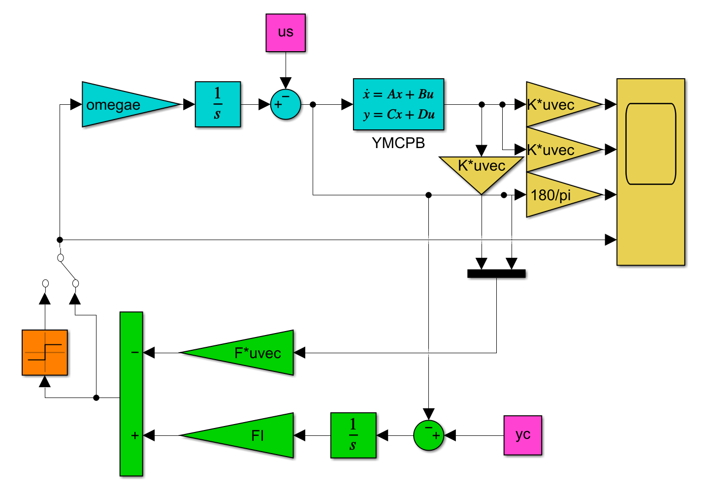
図1 LQI制御系シミュレーション
これを実行して次のシミュレーション結果を得ます。
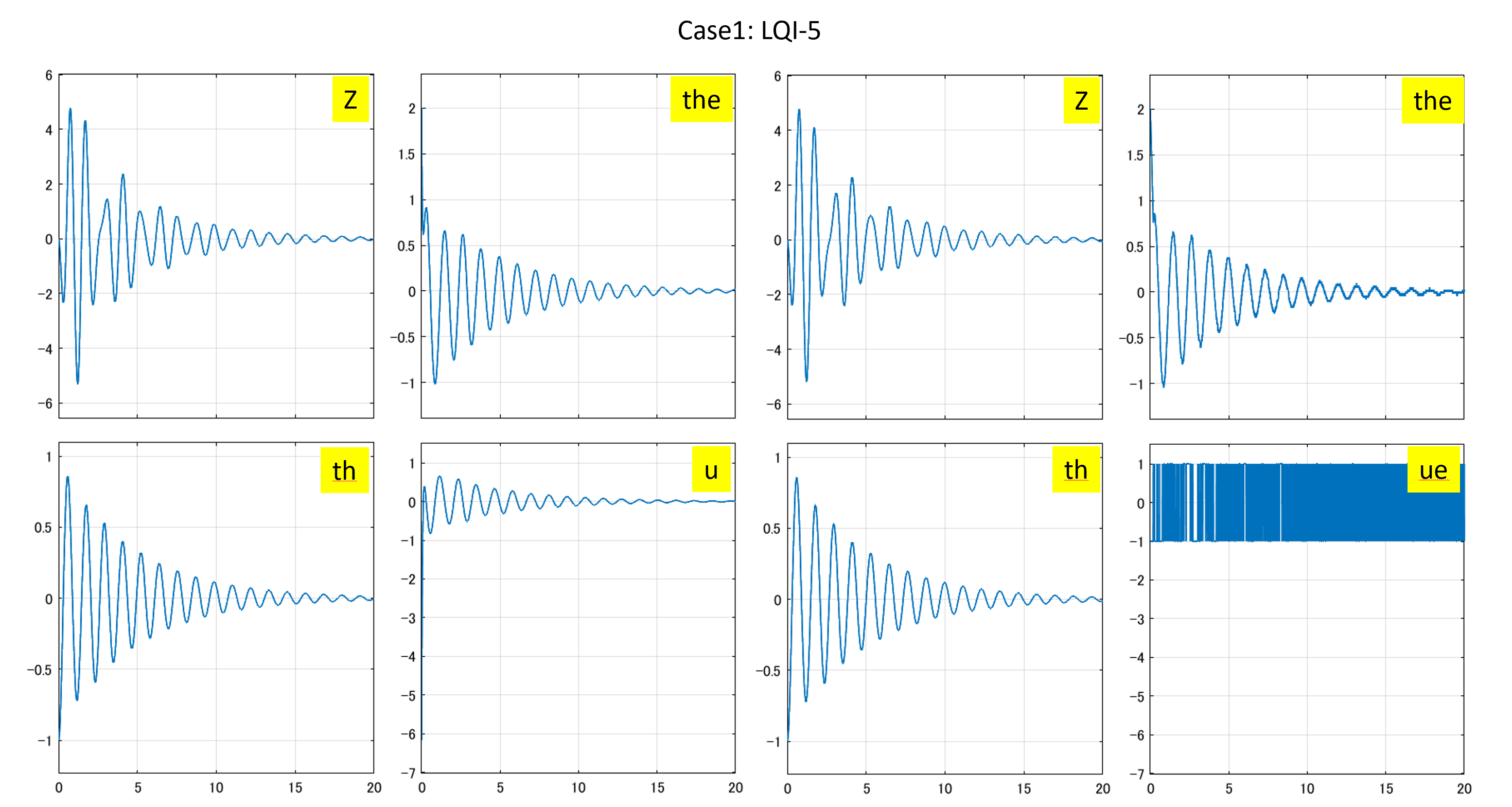
図1 5次元モデルに基づくLQI制御系と符号関数を通したLQI制御
Case 2:Case1でヒーブゲインを零とする場合
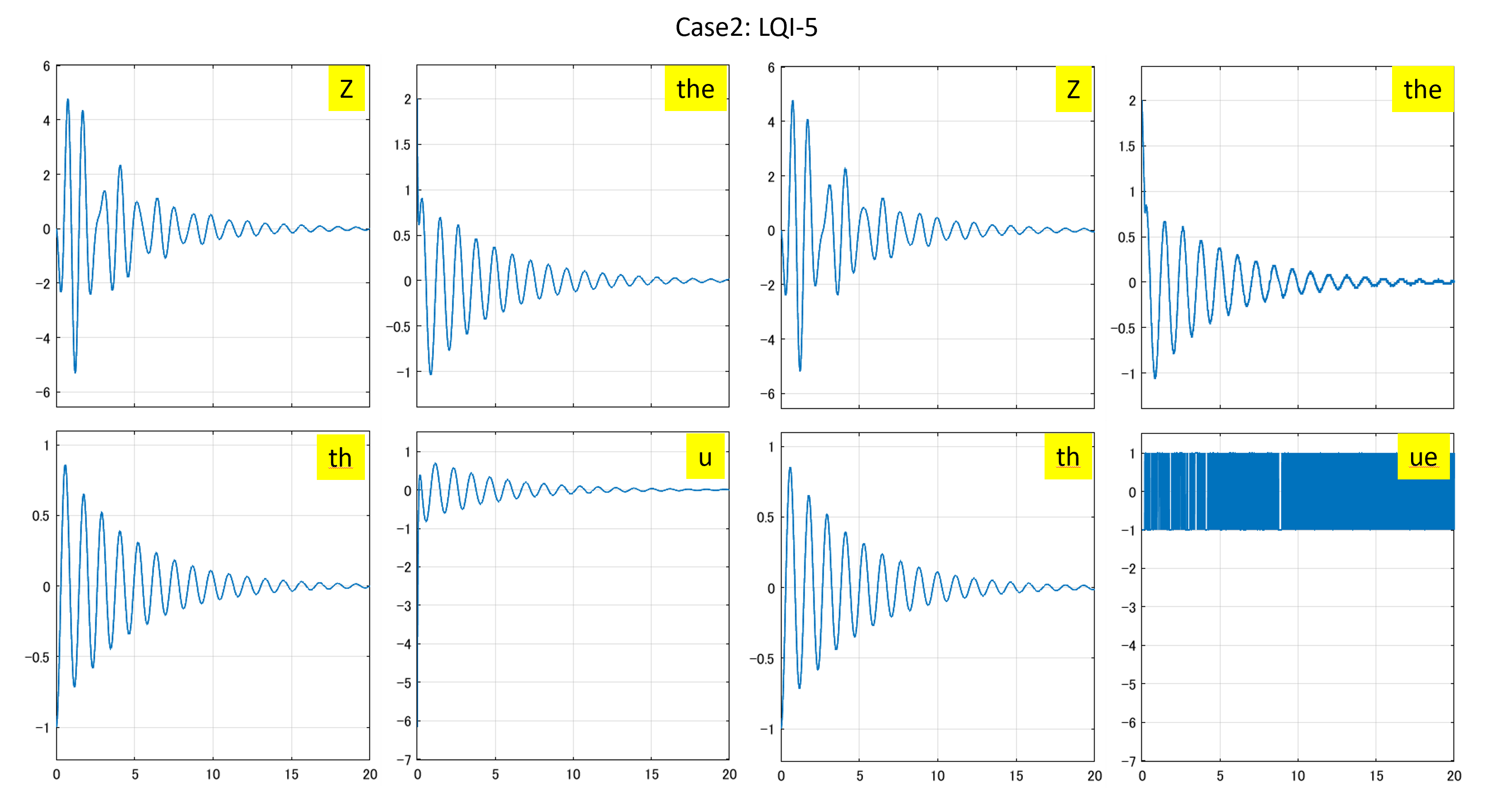
図2 ヒーブゲインを零とした場合のLQI制御系と符号関数を通したLQI制御
Case 3:3次元モデルに基づくLQI制御
●制御対象YMCPBに対するLQI制御系を設計するプログラムを次に示します。
| MATLAB |
|
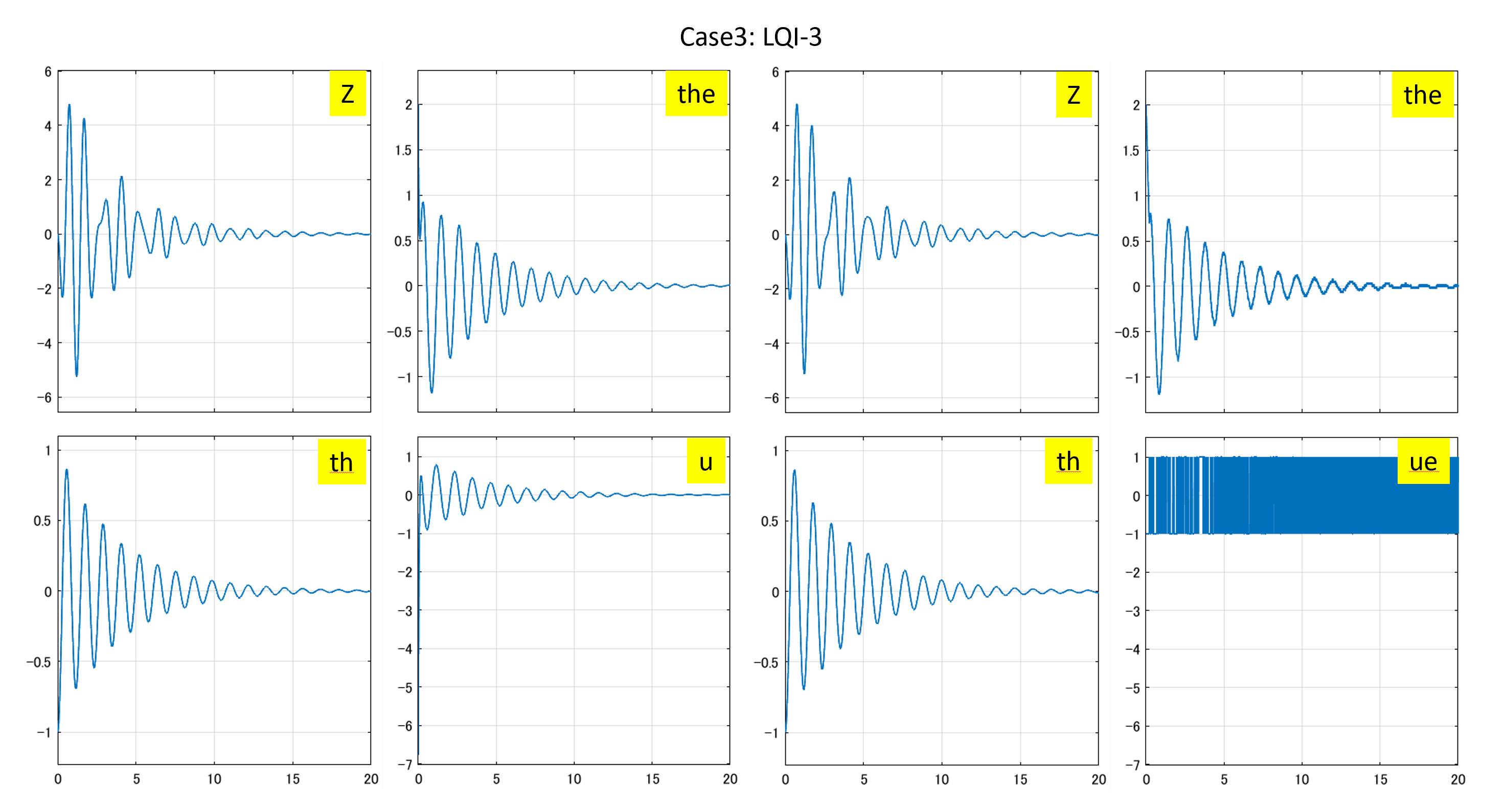
図3 3次元モデルに基づくLQI制御系と符号関数を通したLQI制御
Case 4:Case 1で状態オブザーバを用いる場合
いま、観測変数が状態変数の最初にくるように、状態方程式と観測方程式における状態変数の順番を変えておきます。
![Rendered by QuickLaTeX.com \displaystyle{(11)\quad \begin{array}{l} \underbrace{ \frac{d}{dt} \left[\begin{array}{c} \theta(t)-\theta^*\\ \dot{\theta}(t)\\ \theta_e(t)\\\hline z(t)-z^*\\ \dot{z}(t) \end{array}\right] }_{\dot{x}'(t)} = \underbrace{ \left[\begin{array}{ccc|cc} 0 & 1 & 0 & 0 & 0 \\ a_{63} & 0 & b_{62} & a_{62} & 0 \\ 0 & 0 & 0 & 0 & 0 \\\hline 0 & 0 & 0 & 0 & 1 \\ a_{53} & 0 & b_{52} & a_{52} & 0 \end{array}\right] }_{A'=\left[\begin{array}{cc} A'_{11} & A'_{12}\\ A'_{21} & A'_{22} \end{array}\right] } \underbrace{ \left[\begin{array}{c} \theta(t)-\theta^*\\ \dot{\theta}(t)\\ \theta_e(t)\\\hline z(t)-z^*\\ \dot{z}(t) \end{array}\right] }_{x'(t)}\\ + \underbrace{ \left[\begin{array}{c} 0 \\ 0 \\ \omega_e\\\hline 0 \\ 0 \end{array}\right] }_{B'=\left[\begin{array}{cc} B'_1 \\ B'_2 \end{array}\right] } u(t) \end{array}}](https://cacsd1.sakura.ne.jp/wp/wp-content/ql-cache/quicklatex.com-7fe85e46a1e1633fe91083e8fe93f2a6_l3.png)
![Rendered by QuickLaTeX.com \displaystyle{(12)\quad \begin{array}{l} \underbrace{ \left[\begin{array}{c} \theta(t)-\theta^*\\ \dot{\theta}(t)\\ \theta_e(t) \end{array}\right] }_{y(t)} = \underbrace{ \left[\begin{array}{ccc|cc} 1 & 0 & 0 & 0 & 0 \\ 0 & 1 & 0 & 0 & 0 \\ 0 & 0 & 1 & 0 & 0 \end{array}\right] }_{C'=[I_p\ 0]} \underbrace{ \left[\begin{array}{c} \theta(t)-\theta^*\\ \dot{\theta}(t)\\ \theta_e(t)\\\hline z(t)-z^*\\ \dot{z}(t) \end{array}\right] }_{x'(t)} \end{array}}](https://cacsd1.sakura.ne.jp/wp/wp-content/ql-cache/quicklatex.com-26aac13c924dceec92a99cbc241a9571_l3.png)
このとき、![]() を
を
![Rendered by QuickLaTeX.com \displaystyle{(13)\quad U= \underbrace{\left[\begin{array}{ccc|cc} -\ell_{11} & -\ell_{12} & -\ell_{13} & 1 & 0 \\ -\ell_{21} & -\ell_{22} & -\ell_{23} & 0 & 1 \end{array}\right]}_{[-L\ I_{n-p}]} }](https://cacsd1.sakura.ne.jp/wp/wp-content/ql-cache/quicklatex.com-aa240c9d826b64c2ad7995e2b3c6a247_l3.png)
のように選んで、オブザーバのパラメータを次のように求めることができます。
![]()
![Rendered by QuickLaTeX.com \displaystyle{(15)\quad \begin{array}{l} \left[\begin{array}{cc} \hat{A} & \hat{B} \end{array}\right]=UA' \left[\begin{array}{cc} U\\ C' \end{array}\right]^{-1}= \left[\begin{array}{cc} -L & I_{n-p} \end{array}\right] \left[\begin{array}{cc} A'_{11} & A'_{12}\\ A'_{21} & A'_{22} \end{array}\right] \left[\begin{array}{cc} 0 & I_p\\ I_{n-p}& L \end{array}\right]\\ =\left[\begin{array}{cc} A'_{22}-LA'_{12} & A'_{21}-LA'_{11}+\hat{A}L \end{array}\right] \end{array} }](https://cacsd1.sakura.ne.jp/wp/wp-content/ql-cache/quicklatex.com-6668ff8720ac61955f63a1c860c85b76_l3.png)
![]()
ここで、設計パラメータはサイズ![]() の行列
の行列![]() で
で
![Rendered by QuickLaTeX.com \displaystyle{(17)\quad \hat{A} = \underbrace{\left[\begin{array}{ccc} 0 & 1 \\ a_{52} & 0 \end{array}\right]}_{A'_{22}}- \underbrace{\left[\begin{array}{ccc} \ell_{11} & \ell_{12} & \ell_{13} \\ \ell_{21} & \ell_{22} & \ell_{23} \end{array}\right]}_{L} \underbrace{\left[\begin{array}{ccc} 0 & 0 \\ a_{62} & 0 \\ 0 & 0 \end{array}\right]}_{A'_{12}} }](https://cacsd1.sakura.ne.jp/wp/wp-content/ql-cache/quicklatex.com-1f96c4d67fd044922c91fa9e1e1b2e71_l3.png)
を安定行列とするように選びます。そのためには、仮想システムに対する状態フィードバックによる安定化問題
![Rendered by QuickLaTeX.com \displaystyle{ \begin{array}{cl} (18.1) &\left[\begin{array}{c} \dot{w}_1 \\ \dot{w}_2 \end{array}\right] = \underbrace{\left[\begin{array}{ccc} 0 & a_{52} \\ 1 & 0 \end{array}\right]}_{A'_{22}^T} \left[\begin{array}{c} w_1 \\ w_2 \end{array}\right]+ \underbrace{\left[\begin{array}{ccc} 0 & a_{62} & 0 \\ 0 & 0 & 0 \end{array}\right]}_{A'_{12}^T} \left[\begin{array}{c} v_1 \\ v_2 \\ v_3 \end{array}\right]\\ (18.2) &\left[\begin{array}{c} v_1 \\ v_2 \\ v_3 \end{array}\right]=- \underbrace{\left[\begin{array}{ccc} \ell_{11} & \ell_{21} \\ \ell_{12} & \ell_{22} \\ \ell_{13} & \ell_{23} \end{array}\right]}_{L^T} \left[\begin{array}{c} w_1 \\ w_2 \end{array}\right] \end{array} }](https://cacsd1.sakura.ne.jp/wp/wp-content/ql-cache/quicklatex.com-0966560b08e71e8b9d05e93d3d1a2b46_l3.png)
すなわち
![Rendered by QuickLaTeX.com \displaystyle{ \begin{array}{cl} (19.1) &\left[\begin{array}{c} \dot{w}_1 \\ \dot{w}_2 \end{array}\right] = \left[\begin{array}{ccc} 0 & a_{52} \\ 1 & 0 \end{array}\right] \left[\begin{array}{c} w_1 \\ w_2 \end{array}\right]+ \left[\begin{array}{c} a_{62} \\ 0 \end{array}\right]v_2\\ (19.2) &v_2=- \left[\begin{array}{ccc} \ell_{12} & \ell_{22} \end{array}\right] \left[\begin{array}{c} w_1 \\ w_2 \end{array}\right] \end{array} }](https://cacsd1.sakura.ne.jp/wp/wp-content/ql-cache/quicklatex.com-2207f89283b711b6a3dac5da3343613c_l3.png)
を解けばよいと言えます(![]() 、
、![]() )。
)。