YMCPBのSMI制御

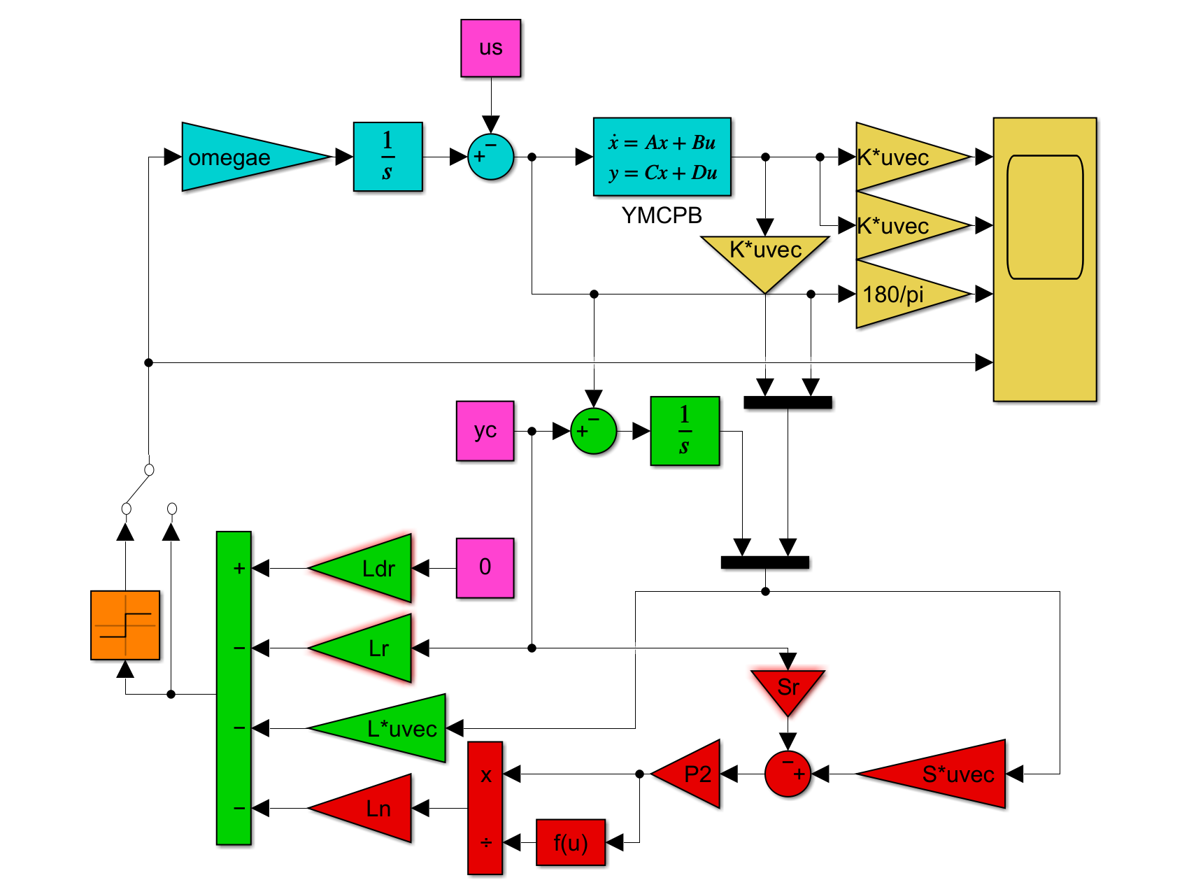
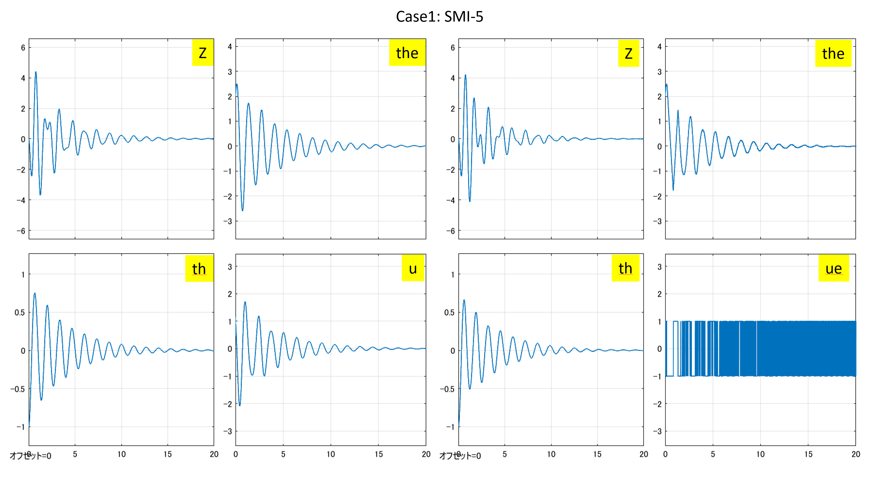
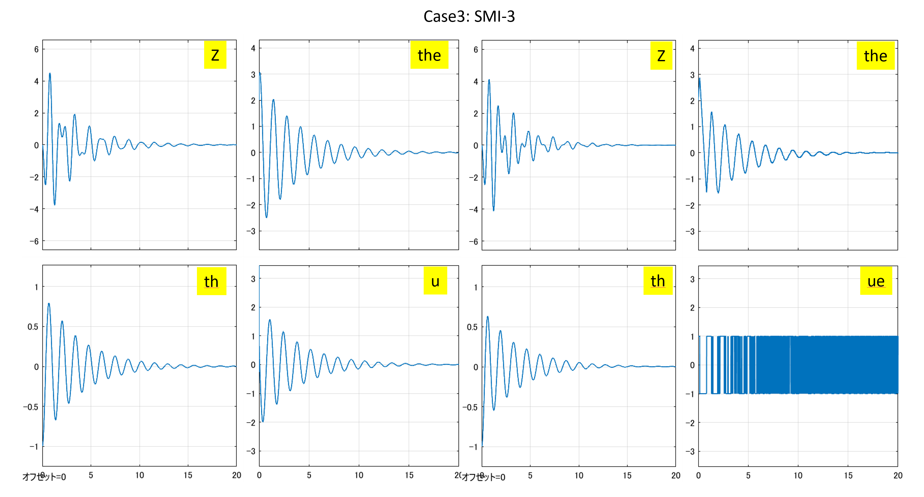
ここでは、次の4種類の積分動作をもつスライディングモード制御(SMI制御)系の設計について述べます。

Case 設計モデル 状態FB 状態OB 積分動作 注意点
1 5次 5次 未使用 「絵に描いた餅」
2 5次 3次 不要 ヒーブのゲインを強制的に零
3 3次 3次 不要 ヒーブからの連成を抑制できるか
4 5次 5次 コントローラが微分方程式

Note e13に示すように、データセットNo.1について、id=128の場合を設計用モデルとして採用したとき、Case2とCase3のどちらを用いても制御性能に大きな差異が見られません。そこでこのコントローラがどれくらいのモデル変動をカバーできるかという意味のロバスト性をシミュレーションにより調べてみます。ここで、モデル変動としては、前進速度を変える場合と、重心位置を変える場合の2通りを考えます。そのために次の3組のデータセットを考えます。

艇質量[kg] 長手方向重心位置[m] 備考
No3 SPTM247 2845 1.937 2022/1/19重量重心測定結果より
No4 SPTM247 2945 1.937 No3重量に+100kg
No5 SPTM247 2745 1.937 No3重量に-100kg

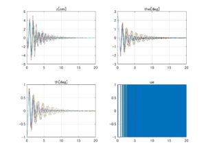
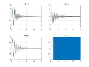
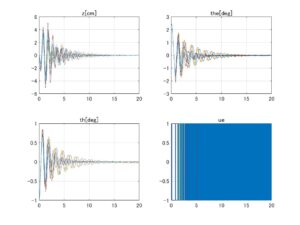
設計用モデルとして、データセットNo.3における船外機取付角-2[deg]のときのid=128の場合を採用し、Case 2とCase 3のLQIコントローラを設計します。そしてデータセットNo.3,4,5における船外機取付角-2[deg]のときのモデル(id=126~133)を安定化できるかを調べます。シミュレーション結果を次に示します。
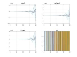
⇒Case2:いくつかの動作点で不安定
⇒Case3:すべて安定
図1 データセットNo.3の場合、SMIコントローラのロバスト性
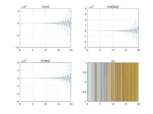
⇒Case2:いくつかの動作点で不安定
⇒Case3:すべて安定
図2 データセットNo.4の場合、SMIコントローラのロバスト性
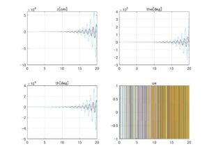
⇒Case2:いくつかの動作点で不安定
⇒Case3:すべて安定
図3 データセットNo.5の場合、SMIコントローラのロバスト性

これらのシミュレーションは本来は非線形シミュレータ上で行うべきですが、ここでは6次元線形モデルを用いて簡易的に行っています。

第1の注意点は、6次元線形モデルの第4番目の状態変数\dot{x}(t)-V^*の係数を強制的にa_{44}=0としていることです。これはa_{44}>0となる場合があって、\dot{x}(t)-V^*が発散してしまうからです。

第2の注意点は、上のシミュレーションではCase 2のコントローラではすべてを安定化できていませんが、設計用モデルとして、データセットNo.1における船外機取付角-2[deg]のときのid=128の場合を採用すると、すべて安定化されることです。

これらの事情は、線形モデルが暫定版の非線形シミュレータから得られているので正確ではないためとも考えられます。いずれにしてもできるだけ実機のダイナミックスを反映した非線形シミュレータ上での再検討が必要になります。

MATLAB
%cYMCPB5_robust_smi.m
%-----
 clear all, close all
 dataset=[...
 "ABC_No1_20220128",...
 "ABC_No2_20220131",...
 "ABC_No3_20220128",...
 "ABC_No4_20220131",...
 "ABC_No5_20220131"];
%-----設計用データセット
 no=3
 load(dataset(no))
 ID=[7,8,9,10,11,12,13,14,...
 36,37,38,39,40,41,42,43,...
 66,67,68,69,70,71,72,73,...
 96,97,98,99,100,101,102,103,...
 126,127,128,129,130,131,132,133];
%-----6次元モデル
%(1)x,(2)z,(3)th,(4)dx-V*,(5)dz,(6)dth
 sys=ss(A0(:,:,ID),B0(:,:,ID),eye(6,6),[]);
%-----5次元モデル
%(1)z,(2)th,(3)dz,(4)dth,(5)the
 k=[2,3,5,6]; i=[2,4,5]; j=[2];
 for id=ID
   A(:,:,id)=[A0(k,k,id) B0(k,j,id);zeros(1,5)];
 end 
 omegae=0.0380*3;
 B=[zeros(4,1);omegae];
 E=eye(5,5);
 CM=E(i,:);
 C=CM(3,:);
 sys5=ss(A(:,:,ID),B,eye(5,5),[]);  
%-----設計ポイント 
 index=35 %[3,11,19,27,35]
 id=ID(index); 
 Vs=dx_eq_Series(id);    %*3.6
 zs=z_eq_Series(id);     %*100
 ths=th_eq_Series(id);   %/pi*180
 thes=the_eq_Series(id); %/pi*180
 [Asys,Bsys,Csys,Dsys]=ssdata(sys(:,:,index));
 [A,B]=ssdata(sys5(:,:,index));
%----- 
% Commands to make a unit vec tor controller incorporating integral action.
% It assumes the triple (A,B,C) is already in regular form
% For simplicity robust pole placement is used for the hyperplane design
% (with suitable modification any of the methods in chap 4 could be used)
% the nth order vector p1 specifies the reduced order motion poles
% the mth order vector p2 specifies  robust pole placement
% the range space dynamics
%-----
 [nn,mm]=size(B);
 [pp,nn]=size(C);
% Augment the orignal (A,B) with the integrator states
 bigA=[zeros(pp,pp) -C;
       zeros(nn,pp) A];
 bigB=[zeros(pp,mm);
       B];
% Since it is assumed that (A,B) is in regular form the augmented 
% pair (bigA,bigB) is also automatically in refular form
 A11=bigA(1:pp+nn-mm,1:pp+nn-mm);
 A12=bigA(1:pp+nn-mm,nn+pp-mm+1:nn+pp);
 B2=bigB(nn+pp-mm+1:nn+pp,:);
% Hyperplane design using robust pole placement
 j=sqrt(-1);
 p1=[-4.7/20+j*4.7, -4.7/20-j*4.7, -7.8/20+j*7.8, -7.8/20-j*7.8, -2/10];
 M=place(A11,A12,p1);
 A11s=A11-A12*M;
 S2=eye(mm)  % For simplicity
 S=S2*[M eye(mm)];
% Form the range space dynamics system matrix
 p2=-1
 Phi=diag(p2,0);
 P2hat=lyap(Phi,eye(mm));
 P2=inv(P2hat);
% Calculate the time varying component of the switching function
 Br=[eye(pp);
     zeros(nn-mm,pp)];
 Sr=-S2*inv(Br'*inv(A11s)*A12)*Br'*inv(A11s)*Br;
% Computes the gains for the feedback and feed-forward components
 L=-inv(S*bigB)*S*bigA+inv(S*bigB)*Phi*S
 L(2)=0; L(4)=0;
 Lr=-inv(S*bigB)*(Phi*Sr+S(:,1:pp))
 Ldr=inv(S*bigB)*Sr
 rho=1
 Ln=inv(S*bigB)*rho
%-----全モデルに対するシミュレーション
for no=[3,4,5] 
for iSIM=index-2:index+5
 id=ID(iSIM);
 Vs=dx_eq_Series(id);    %*3.6
 zs=z_eq_Series(id);     %*100
 ths=th_eq_Series(id);   %/pi*180
 thes=the_eq_Series(id); %/pi*180
 [Asys,Bsys,Csys,Dsys]=ssdata(sys(:,:,iSIM));
 Asys(4,4)=0;
 [A,B]=ssdata(sys5(:,:,iSIM));  
 us=thes;
 xs=[0;zs;ths;Vs;0;0];
 x0=[0;0;-1/180*pi;0;0;0];
 yc=0; 
 E=eye(6,6);
 CM=E([2,3,5,6],:);
 CM1=100*E([2],:);
 CM2=180/pi*E([3],:);
 ns=4;
 simout=sim('nYMCPB_smi.slx');
%[no,iSIM,id,180/pi*us]
 figure(no)
 subplot(221),plot(simout.x.Time,100*simout.x.Data(:,2)),hold on
 subplot(223),plot(simout.y.Time,180/pi*simout.y.Data(:,1)),hold on
 subplot(222),plot(simout.y.Time,180/pi*simout.y.Data(:,3)),hold on
 subplot(224),plot(simout.u.Time,simout.u.Data),hold on
end %iSIM
 figure(no)
 subplot(221),title("z[cm]"),grid
 subplot(223),title("th[deg]"),grid
 subplot(222),title("the[deg]"),grid
 subplot(224),title("ue"),grid
end %no 
%-----
%eof
MATLAB
%cYMCPB3_robust_smi.m
%-----
 clear all, close all
 dataset=[...
 "ABC_No1_20220128",...
 "ABC_No2_20220131",...
 "ABC_No3_20220128",...
 "ABC_No4_20220131",...
 "ABC_No5_20220131"];
%-----設計用データセット
 no=3
 load(dataset(no))
 ID=[7,8,9,10,11,12,13,14,...
 36,37,38,39,40,41,42,43,...
 66,67,68,69,70,71,72,73,...
 96,97,98,99,100,101,102,103,...
 126,127,128,129,130,131,132,133];
%-----6次元モデル
%(1)x,(2)z,(3)th,(4)dx-V*,(5)dz,(6)dth
 sys=ss(A0(:,:,ID),B0(:,:,ID),eye(6,6),[]);
%-----3次元モデル
%(1)th,(2)dth,(3)the
 k=[3,6]; j=[2];
 for id=ID
   AA(:,:,id)=[A0(k,k,id) B0(k,j,id);zeros(1,3)];
 end 
 omegae=0.0380*3;
 B=[zeros(2,1);omegae];
 E=eye(3,3);
 C=E(3,:);
 sys3=ss(AA(:,:,ID),B,eye(3,3),[]);  
%-----設計ポイント 
 index=35 %[3,11,19,27,35]
 id=ID(index); 
 Vs=dx_eq_Series(id);    %*3.6
 zs=z_eq_Series(id);     %*100
 ths=th_eq_Series(id);   %/pi*180
 thes=the_eq_Series(id); %/pi*180
 [Asys,Bsys,Csys,Dsys]=ssdata(sys(:,:,index));
 [A,B]=ssdata(sys3(:,:,index));
%----- 
% Commands to make a unit vec tor controller incorporating integral action.
% It assumes the triple (A,B,C) is already in regular form
% For simplicity robust pole placement is used for the hyperplane design
% (with suitable modification any of the methods in chap 4 could be used)
% the nth order vector p1 specifies the reduced order motion poles
% the mth order vector p2 specifies  robust pole placement
% the range space dynamics
%-----
 [nn,mm]=size(B);
 [pp,nn]=size(C);
% Augment the orignal (A,B) with the integrator states
 bigA=[zeros(pp,pp) -C;
       zeros(nn,pp) A];
 bigB=[zeros(pp,mm);
       B];
% Since it is assumed that (A,B) is in regular form the augmented 
% pair (bigA,bigB) is also automatically in refular form
 A11=bigA(1:pp+nn-mm,1:pp+nn-mm);
 A12=bigA(1:pp+nn-mm,nn+pp-mm+1:nn+pp);
 B2=bigB(nn+pp-mm+1:nn+pp,:);
% Hyperplane design using robust pole placement
 j=sqrt(-1);
 p1=[-4.7/20+j*4.7, -4.7/20-j*4.7, -2/10];
 M=place(A11,A12,p1);
 A11s=A11-A12*M;
 S2=eye(mm)  % For simplicity
 S=S2*[M eye(mm)];
% Form the range space dynamics system matrix
 p2=-1
 Phi=diag(p2,0);
 P2hat=lyap(Phi,eye(mm));
 P2=inv(P2hat);
% Calculate the time varying component of the switching function
 Br=[eye(pp);
     zeros(nn-mm,pp)];
 Sr=-S2*inv(Br'*inv(A11s)*A12)*Br'*inv(A11s)*Br;
% Computes the gains for the feedback and feed-forward components
 L=-inv(S*bigB)*S*bigA+inv(S*bigB)*Phi*S
 Lr=-inv(S*bigB)*(Phi*Sr+S(:,1:pp))
 Ldr=inv(S*bigB)*Sr
 rho=1
 Ln=inv(S*bigB)*rho 
%-----全モデルに対するシミュレーション
for no=[3,4,5] 
for iSIM=index-2:index+5
 id=ID(iSIM);
 Vs=dx_eq_Series(id);    %*3.6
 zs=z_eq_Series(id);     %*100
 ths=th_eq_Series(id);   %/pi*180
 thes=the_eq_Series(id); %/pi*180
 [Asys,Bsys,Csys,Dsys]=ssdata(sys(:,:,iSIM));
 Asys(4,4)=0;
 [A,B]=ssdata(sys3(:,:,iSIM));    
 us=thes;
 xs=[0;zs;ths;Vs;0;0];
 x0=[0;0;-1/180*pi;0;0;0];
 yc=0; 
 E=eye(6,6);
 CM=E([3,6],:);
 CM1=100*E([2],:);
 CM2=180/pi*E([3],:);
 ns=2;
 simout=sim('nYMCPB_smi.slx');
%[no,iSIM,id,180/pi*us]
 figure(no)
 subplot(221),plot(simout.x.Time,100*simout.x.Data(:,2)),hold on
 subplot(223),plot(simout.y.Time,180/pi*simout.y.Data(:,1)),hold on
 subplot(222),plot(simout.y.Time,180/pi*simout.y.Data(:,3)),hold on
 subplot(224),plot(simout.u.Time,simout.u.Data),hold on
end %iSIM
 figure(no)
 subplot(221),title("z[cm]"),grid
 subplot(223),title("th[deg]"),grid
 subplot(222),title("the[deg]"),grid
 subplot(224),title("ue"),grid
end %no  
%-----
%eof

Note e13 SMI制御系の設計
Case 1:5次元モデルに基づくSMI制御

●制御対象

\displaystyle{(1)\quad \begin{array}{l} \dot{x}(t)=Ax(t)+Bu(t)\\ y(t)=Cx(t)\\ (x(t)\in{\rm\bf R}^n, u(t)\in{\rm\bf R}^m, y(t)\in{\rm\bf R}^p, m=p) \end{array} }

の出力を、コマンド(次式の解)

\displaystyle{(2)\quad \begin{array}{l} %\dot{r}(t)=\Gamma(r(t)-r_c)\\ \frac{d}{dt}(r(t)-r_c)=\Gamma(r(t)-r_c)\\ (r(t),r_c\in{\rm\bf R}^m) \end{array} }

に追従させることを考えます(\Gammaは安定行列)。そのために、積分動作

\displaystyle{(3)\quad \begin{array}{l} \dot{x}_r(t)=r(t)-y(t)\\ (x_r(t)\in{\rm\bf R}^m) \end{array} }

を導入し、次の拡大系を構成します。ここで、(1)はすでに標準形であるとしています。

\displaystyle{(4)\quad \begin{array}{l} \left[\begin{array}{c} \dot x_r(t)\\ \dot x(t) \end{array}\right] = \left[\begin{array}{c|cc} 0 & -C_1 & -C_2\\\hline 0 & A_{11} & A_{12} \\ 0 & A_{21} & A_{22} \end{array}\right] \left[\begin{array}{c} x_r(t)\\ x(t) \end{array}\right] + \left[\begin{array}{c} 0\\\hline 0\\ B_2 \end{array}\right] u(t) + \left[\begin{array}{c} I_m \\\hline 0 \\ 0 \end{array}\right] r(t)\\ (x_r(t)\in{\rm\bf R}^m, x(t)\in{\rm\bf R}^n) \end{array} }

これを、次のように分割し直しても標準形であることには変わりありません。

\displaystyle{(5a)\quad \begin{array}{l} \left[\begin{array}{c} \dot{x}_1(t)\\ \dot{x}_2(t) \end{array}\right] = \underbrace{ \left[\begin{array}{cc|c} 0 & -C_1 & -C_2\\ 0 & A_{11} & A_{12} \\\hline 0 & A_{21} & A_{22} \end{array}\right] }_{A_E} \left[\begin{array}{c} x_1(t)\\ x_2(t) \end{array}\right] + \underbrace{ \left[\begin{array}{c} 0\\ 0\\\hline B_2 \end{array}\right] }_{B_E} u(t) + \left[\begin{array}{c} I_m \\ 0 \\\hline 0 \end{array}\right] r(t)\\ (x_1(t)\in{\rm\bf R}^n, x_2(t)\in{\rm\bf R}^m) \end{array} }

ただし

\displaystyle{(5b)\quad %\begin{array}{l} \left[\begin{array}{c} x_1(t)\\ x_2(t) \end{array}\right] = \left[\begin{array}{c} x_r(t)\\ x(t) \end{array}\right] %\end{array} }

●この積分器による拡大系を安定化できれば、積分器の値x_r(t)は定値となり、被積分項r(t)-y(t)の値は零となり、y(t)r(t)へ漸近します。そこで、SM制御によって拡大系を安定化し、追従制御系を構成することを考えます。この制御系は特別なr(t)=0の場合を含みますので、まずスイッチング関数として、次式を考えます。

\displaystyle{(6)\quad s(t)= \underbrace{ \left[\begin{array}{cc} S_1 & S_2 \\ \end{array}\right] }_{S} %\underbrace{ \left[\begin{array}{c} x_1(t)\\ x_2(t) \end{array}\right] %}_{x(t)} = \underbrace{S_2 \left[\begin{array}{cc} M & I_m \\ \end{array}\right] }_{S} %\underbrace{ \left[\begin{array}{c} x_1(t)\\ x_2(t) \end{array}\right] %}_{x(t)} \ (M=S_2^{-1}S_1) }

(5)に対して、座標変換

\displaystyle{(7)\quad \begin{array}{l} \left[\begin{array}{c} x_1(t)\\ s(t) \end{array}\right] = \underbrace{ \left[\begin{array}{cc} I_n & 0 \\ S_1 & S_2 \\ \end{array}\right] }_{T_s} \left[\begin{array}{c} x_1(t)\\ x_2(t) \end{array}\right]\\ \Leftrightarrow \left[\begin{array}{c} x_1(t)\\ x_2(t) \end{array}\right] = \underbrace{ \left[\begin{array}{cc} I_n & 0 \\ -S_2^{-1}S_1 & S_2^{-1} \\ \end{array}\right] }_{T_s^{-1}} \left[\begin{array}{c} x_1(t)\\ s(t) \end{array}\right] \end{array} }

を行って、次式を得ます。

\displaystyle{(8a)\quad \begin{array}{l} %\underbrace{ \left[\begin{array}{c} \dot x_1(t)\\ \dot s(t) \end{array}\right] %}_{\dot{x}'(t)} = \underbrace{ \left[\begin{array}{cc} \bar{A}_{11} & \bar{A}_{12} \\ S_2\bar{A}_{21} & S_2\bar{A}_{22}S_2^{-1} \\ \end{array}\right] }_{T_sA_ET_s^{-1}} %\underbrace{ \left[\begin{array}{c} x_1(t)\\ s(t) \end{array}\right] %}_{x'(t)} + \underbrace{ \left[\begin{array}{cc} 0\\ S_2B_2 \end{array}\right] }_{T_sB_E} u(t)\\ + \left[\begin{array}{cc} B_r \\ S_1B_r \end{array}\right] r(t) \end{array} }

ただし

\displaystyle{(8b)\quad \left\{\begin{array}{l} \bar{A}_{11}= \left[\begin{array}{cc} 0 & -C_1 \\ 0 & A_{11} \end{array}\right] -\left[\begin{array}{c} -C_2\\ A_{12} \end{array}\right]M\\ \bar{A}_{12}= \left[\begin{array}{c} -C_2\\ A_{12} \end{array}\right]S_2^{-1}\\ \bar{A}_{21}=S_2(M\bar{A}_{11} + \left[\begin{array}{cc} 0 & A_{21} \end{array}\right] -A_{22}M)\\ \bar{A}_{22}=S_2(M \left[\begin{array}{c} -C_2\\ A_{12} \end{array}\right] +A_{22})S_2^{-1}\\ B_r=\left[\begin{array}{cc} I_m \\ 0 \end{array}\right] \end{array}\right. }

ここで、\bar{A}_{11}が安定行列となるように行列Mが選ばれているとします。

●このときSM制御則は次式で与えられます。

\displaystyle{(9)\quad { \boxed{\begin{array}{l} u(t)=u_\ell(t)+u_n(t)\\ u_\ell(t)=-\underbrace{(SB_E)^{-1}(SA_E-\Phi S)}_{L=L_{eq}+L_\Phi}\left[\begin{array}{c} x_r(t)\\ x(t) \end{array}\right]\\ -\underbrace{(SB_E)^{-1}(\Phi S_r+S_1B_r)}_{L_r} r(t) +\underbrace{(SB_E)^{-1}S_r}_{L_{\dot r}} \dot{r}(t)\\ u_n(t)=-\underbrace{(SB_E)^{-1}\rho(t,x)}_{L_n}\frac{P_2(s(t)-S_rr(t))}{||P_2(s(t)-S_rr(t))||} \end{array}}} }

MATLAB
%cYMCPB5_smi.m
%-----
 clear all, close all
 dataset=[...
 "ABC_No1_20220128",...
 "ABC_No2_20220131",...
 "ABC_No3_20220128",...
 "ABC_No4_20220131",...
 "ABC_No5_20220131"];
 no=1
 load(dataset(no))
 ID=[8,9,10,11,12,13,14,...
 36,37,38,39,40,41,42,43,...
 66,67,68,69,70,71,72,73,...
 97,98,99,100,101,102,103,...
 126,127,128,129,130,131,132,133];
%-----6次元モデル
%(1)x,(2)z,(3)th,(4)dx-V*,(5)dz,(6)dth
 sys=ss(A0(:,:,ID),B0(:,:,ID),eye(6,6),[]);
%-----5次元モデル
%(1)z,(2)th,(3)dz,(4)dth,(5)the
 k=[2,3,5,6]; i=[2,4,5]; j=[2];
 for id=ID
   A(:,:,id)=[A0(k,k,id) B0(k,j,id);zeros(1,5)];
 end 
 omegae=0.0380*3;
 B=[zeros(4,1);omegae];
 E=eye(5,5);
 CM=E(i,:);
 C=CM(3,:);
 sys5=ss(A(:,:,ID),B,eye(5,5),[]);  
%-----設計ポイント id=128=ID(33)
 Vs=dx_eq_Series(128);    %*3.6
 zs=z_eq_Series(128);     %*100
 ths=th_eq_Series(128);   %/pi*180
 thes=the_eq_Series(128); %/pi*180
 [Asys,Bsys,Csys,Dsys]=ssdata(sys(:,:,33));
 [A,B]=ssdata(sys5(:,:,33));
%-----
 AE=[0 -C ;
    zeros(5,1) A];
 BE=[0; B];
 lambda=[-4.7/20 4.7 -7.8/20 7.8 -2/10];
 nocomp=2;
 specpos=rand(6,5);
 specent=rand(6,5);
 S=swfvpl(AE,BE,lambda,nocomp,specpos,specent);   
 FE=(S*BE)\(S*AE);
 eig(AE-BE*FE);
%-----
 [nn,mm]=size(B);
 S1=S(:,1:nn-mm);
 S2=S(:,nn-mm+1:nn);
 Br=eye(nn-mm,mm);
 B2=B(nn-mm+1:nn,:); 
 Lambda=S2*B2;
 Phi=-0.5
 P2=0.5*inv(-Phi);
 Leq=inv(S*BE)*S*AE;
 LPhi=-inv(S*BE)*Phi*S;
 rho=2
 Sr=0
%----- 
 L=Leq+LPhi
 Ln=inv(S*BE)*rho
 Lr=inv(Lambda)*(Phi*Sr+S1*Br)
 Ldr=inv(Lambda)*Sr
%L(2)=0; L(4)=0;
%-----
 us=thes;
 xs=[0;zs;ths;Vs;0;0];
 x0=[0;0;-1/180*pi;0;0;0];
 yc=0; 
 E=eye(6,6);
 CM=E([2,3,5,6],:);
 CM1=100*E([2],:);
 CM2=180/pi*E([3],:);
 ns=4;
%-----
%eof
% L =
%    -0.6767   53.6065  -82.8461    3.7131   18.0214    2.8876
% Ln =
%    39.6861
% Lr =
%   -11.3251
% Ldr =
%      0


図1 SMI制御系シミュレーション


図2 5次元モデルに基づくSMI制御系と符号関数を通したSMI制御

Case 2:Case1でヒーブゲインを零とする場合
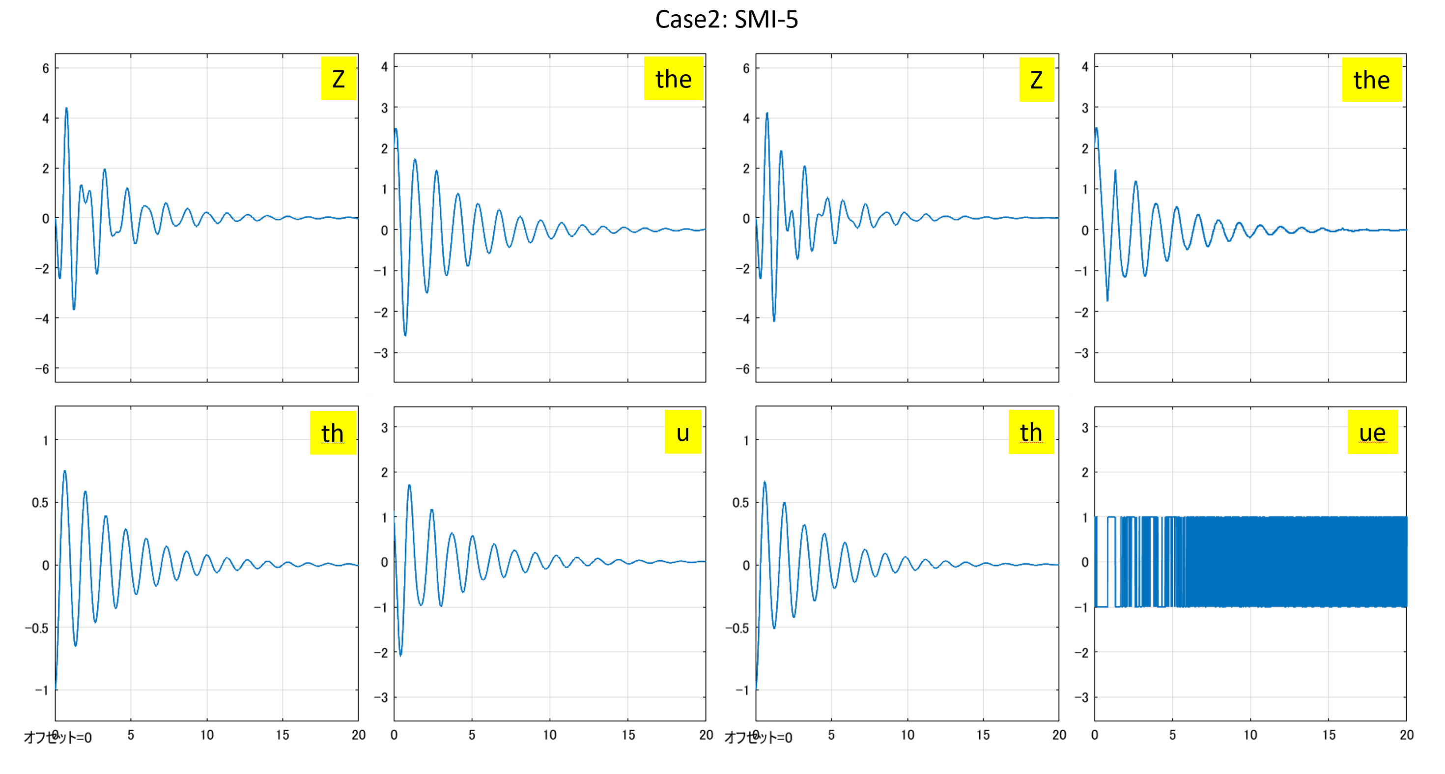

図3 ヒーブゲインを零とした場合のSMI制御系と符号関数を通したSMI制御

Case 3:3次元モデルに基づくSMI制御

●制御対象YMCPBに対するSMI制御系を設計するプログラムを次に示します。

MATLAB
%cYMCPB3_smi.m
%-----
 clear all, close all
 dataset=[...
 "ABC_No1_20220128",...
 "ABC_No2_20220131",...
 "ABC_No3_20220128",...
 "ABC_No4_20220131",...
 "ABC_No5_20220131"];
 no=1
 load(dataset(no))
 ID=[8,9,10,11,12,13,14,...
 36,37,38,39,40,41,42,43,...
 66,67,68,69,70,71,72,73,...
 97,98,99,100,101,102,103,...
 126,127,128,129,130,131,132,133];
%-----6次元モデル
%(1)x,(2)z,(3)th,(4)dx-V*,(5)dz,(6)dth
 sys=ss(A0(:,:,ID),B0(:,:,ID),eye(6,6),[]);
%-----3次元モデル
%(1)th,(2)dth,(3)the
 k=[3,6]; j=[2];
 for id=ID
   AA(:,:,id)=[A0(k,k,id) B0(k,j,id);zeros(1,3)];
 end 
 omegae=0.0380*3;
 B=[zeros(2,1);omegae];
 E=eye(3,3);
 C=E(3,:);
 sys3=ss(AA(:,:,ID),B,eye(3,3),[]);  
%-----設計ポイント id=128,ID=33
 Vs=dx_eq_Series(128);    %*3.6
 zs=z_eq_Series(128);     %*100
 ths=th_eq_Series(128);   %/pi*180
 thes=the_eq_Series(128); %/pi*180
 [Asys,Bsys,Csys,Dsys]=ssdata(sys(:,:,33));
 [A,B]=ssdata(sys3(:,:,33));
%----- 
 AE=[0 -C ;
    zeros(3,1) A];
 BE=[0; B];
 lambda=[-4.7/20 4.7 -2/10];
 nocomp=1;
 specpos=rand(4,3);
 specent=rand(4,3);
 S=swfvpl(AE,BE,lambda,nocomp,specpos,specent);    
 FE=(S*BE)\(S*AE);
 eig(AE-BE*FE);
%---
 [nn,mm]=size(B);
 S1=S(:,1:nn-mm);
 S2=S(:,nn-mm+1:nn);
 Br=eye(nn-mm,mm);
 B2=B(nn-mm+1:nn,:); 
 Lambda=S2*B2;
 Phi=-0.5
 P2=0.5*inv(-Phi);
 Leq=inv(S*BE)*S*AE;
 LPhi=-inv(S*BE)*Phi*S;
 rho=2
 Sr=0
%-----
 L=Leq+LPhi
 Ln=inv(S*BE)*rho
 Lr=inv(Lambda)*(Phi*Sr+S1*Br)
 Ldr=inv(Lambda)*Sr
%-----
 us=thes;
 xs=[0;zs;ths;Vs;0;0];
 x0=[0;0;-1/180*pi;0;0;0];
 yc=0; 
 E=eye(6,6);
 CM=E([3,6],:);
 CM1=100*E([2],:);
 CM2=180/pi*E([3],:);
 ns=2;
%-----
%eof
% L =
%    -0.6402   73.9799   24.2004   11.2935
% Ln =
%    54.0449
% Lr =
%     5.5635
% Ldr =
%      0


図4 3次元モデルに基づくSMI制御系と符号関数を通したSMI制御