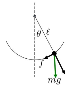
次の単振り子を考えます。

この運動方程式は
![]()
すなわち
![]()
となります。ここで、![]() と近似すると
と近似すると
![]()
となります。この解は、![]() を仮定すると
を仮定すると
![]()
のように表されます。ここで、単振り子の周期は次式で与えられます。
![]()
この線形シミュレーションを行うために、次のプログラムを実行してみてください。
function dx=f(t,x),
dx=A*x,
endfunction
g=9.8; L=1;
A=[0 1;-g/L 0];
t0=0; t1=10; nt=100; td=(t1-t0)/nt; t=t0:td:t1;
x0=[-30/180*%pi;0];
x1=ode(x0,t0,t,f);
x0=[-177/180*%pi;0];
x2=ode(x0,t0,t,f);
clf(0),scf(0);
plot(t,180/%pi*x1(1,:),’b’,t,180/%pi*x2(1,:),’r’),
mtlb_grid
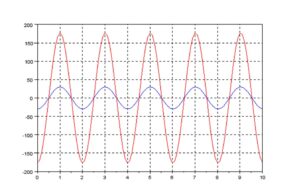
次のようなグラフが現れるでしょう。初期値は2通り設定しています。

次に、非線形シミュレーションを行うために、次のプログラムを実行してみてください。
function dx=f1(t,x)
th=x(1);
dth=x(2);
dx(1)=dth;
dx(2)=-g/ell*sin(th);
endfunction
g=9.8; ell=1; T=2*%pi*1/sqrt(g/ell)
t0=0; t1=10; nt=100; td=(t1-t0)/nt; t=t0:td:t1;
x=[-30/180*%pi;0];
for i=1:nt, x=[x ode(x(:,i),t(i),t(i+1),f1)]; end
x1=x;
x=[-177/180*%pi;0];
for i=1:nt, x=[x ode(x(:,i),t(i),t(i+1),f1)]; end
x2=x;
clf(0),scf(0);
plot(t,180/%pi*x1(1,:),’b’,t,180/%pi*x2(1,:),’r’),
mtlb_grid
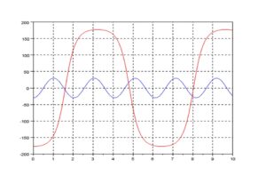
次のようなグラフが現れるでしょう。初期値は2通り設定しています。

線形と非線形では、シミュレーション結果が全く違います!
それでは、これらをアニメーションで比較してみましょう。まず、線形シミュレーションの場合です。
function dx=f1(t,x),
dx=A*x,
endfunction
g=9.8; L=1;
A=[0 1;-g/L 0];
t0=0; t1=10; nt=2000; td=(t1-t0)/nt; t=t0:td:t1;
x0=[-30/180*%pi;0];
x1=ode(x0,t0,t,f1);
x0=[-177/180*%pi;0];
x2=ode(x0,t0,t,f1);
x=L*sin(x2(1,:)+%pi);
y=L*cos(x2(1,:)+%pi);
figure(1);
plot([0;x(1)],[0;y(1)],’o-‘);
h_compound = gce();
h_compound.children.thickness = 2
h_compound.children.mark_size = 10;
h_compound.children.mark_background = 2;
h_axes = gca();
h_axes.data_bounds = [-1.5,-1.5;1.5,1.5];
i = 1;
while i<=length(t)
drawlater();
h_compound.children.data = [0 0;x(i),y(i)];
drawnow();
i = i+1;
end
次に、非線形シミュレーションの場合です。
function dx=f2(t,x)
th=x(1);
dth=x(2);
dx(1)=dth;
dx(2)=-g/ell*sin(th);
endfunction
g=9.8; ell=0.5; T=2*%pi*1/sqrt(g/ell);
t0=0; t1=10; nt=2000; td=(t1-t0)/nt; t=t0:td:t1;
x0=[-30/180*%pi;0];
x1=ode(x0,t0,t,f2);
x0=[-177/180*%pi;0];
x2=ode(x0,t0,t,f2);
x=2*ell*sin(x2(1,:)+%pi);
y=2*ell*cos(x2(1,:)+%pi);
figure(1);
plot([0;x(1)],[0;y(1)],’o-‘);
h_compound = gce();
h_compound.children.thickness = 2
h_compound.children.mark_size = 10;
h_compound.children.mark_background = 2;
h_axes = gca();
h_axes.data_bounds = [-1.5,-1.5;1.5,1.5];
i = 1;
while i<=length(t)
drawlater();
h_compound.children.data = [0 0;x(i),y(i)];
drawnow();
i = i+1;
end
このアニメーションの作成には、次のサイトを参考にさせていただきました。
【参考】 バネで拘束されている台車のアニメーションを以下に示します。
clear; xdel(winsid());
function dx=f(t,x),
dx=A*x,
endfunction
A=[0 1;-1 0];
t0=0; t1=10; nt=2000; td=(t1-t0)/nt; t=t0:td:t1;
x0=[0;1];
x1=ode(x0,t0,t,f);
x=0.2*[0 1 1 0 0]’;
y=0.2*[0 0 1 1 0]’;
figure(1);
plot(x,y);
mtlb_grid
h_compound = gce();
h_compound.children.thickness = 2
h_compound.children.mark_size = 10;
h_compound.children.mark_background = 2;
h_axes = gca();
h_axes.data_bounds = [-1.5,-1;1.5,1];
i = 1;
while i<=length(t)
drawlater();
h_compound.children.data = [x+x1(1,i) y];
drawnow();
i = i+1;
end